Arcane University: Nifskope Hinge Constraints
Hinge constraints can be setup in Nifskope. Their purpose is to “tie” 2 rigid bodies together, allowing a single axis of rotation between them, limited by a minimum and a maximum angle. Some typical use cases for hinge constraints seen in Vanilla are inn signs and books’ world model.
Contents
Nif preparation
Before setting up your hinge constraint, you want to make sure your nif architecture has at least two rigid bodies, each under its own node (Node 2 can be a child of Node 1 though).
The mesh, if there is one, can either be directly placed under the same NiNode as its collision (simple meshes), or exist somewhere else in the nif and be rigged through a Skin Instance to the collision’s node (the node then effectively becoming a bone).
Make sure both rigid bodies are of type bhkRigidBodyT (the T is important), at least the ones that are supposed to be able to move. If they do not have the T, then right click on it, and select Block->Convert->Havok->bhkRigidBodyT. Also ensure that the parent bhkCollisionObject(s) have the flags ACTIVE and SYNC_ON_UPDATE. As a general consideration, to prevent any kind of performance issues, it is recommended that constraints or animation in nifs are applied to fairly simple collision, such as box, sphere, capsule or convex vertices.
Adding the hinge constraints
You only need to set the hinge constraint for 1 of the 2 bodies: The one “that moves relative to the other”.
Alongside the usual bdkRigidBody properties, you need to add a constraints:
Locate the Num Constraints properties, and set them to 1. Then click on the refresh button on the Constraints properties to make the list update with the relevant number of entries:
Then, after expanding the Constraints properties, click on the green + and select bhkLimitedHingeConstraint.
Configuring the limited hinge constraint
Select the bhkLimitedHingeConstraint created previously and set its properties.
Set Num Entities to 2 and refresh the Entities property, as before with the Constraints property. Set the first entry to the block number of the bhkRigidBodyT this constraint is on. Set the second entry to the block number of the bhkRigidBodyT this constraint needs to be set against.
Priority can be left at 1, or set to 1 if it isn't, if you are working on a simple mesh. The exact meaning of this setting is still unknown, although its general purpose is identified as setting priorities between multiple constraints.
Setting hinge coordinates
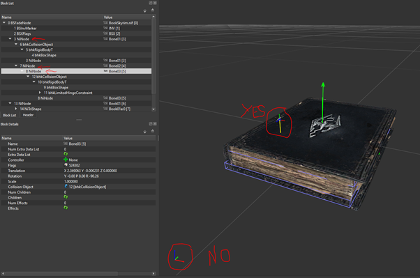
Very important! These coordinates are to be set in the coordinate system of the rigid body, not the world! This is not necessarily the coordinates system displayed in the main Nifskope frame, but the one that appear when you select the node:
In the screenshot above, the coordinate system is rotated relatively to the main model’s coordinate system. This is due to the accumulated Translations and Rotations of all the parent NiNoded indicated in the nif architecture.
The axis of rotation for the constraint can be set in Axis A. The X Y Z W coordinates are a common way of defining vectors in Nif format: X, Y and Z should form a unit vector (i.e. length of 1) and "W" is the "weight", i.e. the length of the defined vector. For the purpose of a simple axis, the weight does not really matter, so it can be set to 1.
Then with the same considerations as above, fill in the Perp Axis in A1, Perp Axis in A2, and Pivot A properties.
- Perp Axis in A1 should be orthogonal to Axis A, and will define the angle 0.
- Perp Axis in A2 is simply the dot product of Axis A and Perp Axis in A1. This is likely put into the model, rather than calculated, so that the engine does not have to compute it each time.
- Pivot A is the coordinates of the pivot point. Here, W needs to be ignored, and only X, Y and Z need to be set.
Then, the same will need to be done for Axis B properties in semi-automated ways. These are the same as their Axis A counterparts except expressed in the coordinate system of the second entity.
Finally, set Min Angle and Max Angle to limit the range of the constraint (in radians, not degrees), and the Max Friction, which will define how strong the constraint will slow/resist the movement.
It is recommended to fine tune these 3 values once the model is final and implemented, to make sure the constraint feels natural once subject to the various things that can happens to it in the engine.
For a simple idle constraint, leave the Motor Type to MOTOR_NONE.
If your bhkRigidBodies and the rest of your Nif architecture is properly setup, your constraint should now work in-game.
As further reference, check https://wiki.beyondskyrim.org/wiki/Arcane_University:Nif_Implementation.
specific topics tutorials
volume physics
- Nif data formate and its structure: https://wiki.beyondskyrim.org/wiki/Arcane_University:NIF_Data_Format
- making a simple mesh rotation animation with Nifskope https://www.youtube.com/watch?v=YmGVknCC_a8
- adjusting size, scale and position of nitrishapes in nifskope: https://www.youtube.com/watch?v=C9rlBDrfSP8
- Animate Static Objects: https://www.youtube.com/watch?v=1lkrX3HYSDc
- Animate Static Objects via NiTransformController: https://www.youtube.com/watch?v=pYcAA09yygI
- copy animations to custom nif: https://www.youtube.com/watch?v=SodgAvvEjwQ
- Shader implementation (Fire on a hut): https://www.youtube.com/watch?v=nGO0gwFwnLs
surface rendering
- DDS texture formate https://wiki.beyondskyrim.org/wiki/Arcane_University:DDS_Data_Format
- editing the UV map https://www.youtube.com/watch?v=1u51yDEGzmQ
- making a simple rotation animation with a texture via UV map in Nifskope https://www.youtube.com/watch?v=CBlaY5keZRg
- placing textures on a nitrishape via nifskope including UV map adjustments: https://www.youtube.com/watch?v=kbnE5MZhdOE

