Arcane University:Rigging with Blender 2.79
This tutorial was written by opusGlass.
This tutorial will cover rigging armors and creatures for Skyrim using Blender 2.79 and assumes you have read Hayden's tutorial for the basics of working on Nifs with Blender.
Contents
Setup[edit]
- Install Blender 2.79b (similar versions might work but are untested, 2.80 does not work as of the last time I tested)
- Install NifTools 2.6.0dev4 from 7/30/2018 MUST BE THIS EXACT VERSION
- Install opusGlass's modifications to the NifTools plugin.
- Locate your NifTools plugin folder in AppData. For me it is %AppData%\Blender Foundation\Blender\2.79
- Navigate to the subfolder \scripts\addons
- Extract the contents of my modifications into this folder. It should ask to overwrite files, click Yes.
- Locate your NifTools plugin folder in AppData. For me it is %AppData%\Blender Foundation\Blender\2.79
- Open Blender and enable the NifTools addon in User Preferences.
First Notes[edit]
Firstly, as a beginner, you will avoid a lot of issues by choosing an existing vanilla creature and using the information from it whenever possible. You should treat this as the Cardinal Rule, only to be deviated from when you know what you are doing. This includes:
- Import the vanilla creature model and modifying it, instead of working from scratch. Even if you don’t want any of the 3D data, you should just delete the triangles to preserve the shader data, etc.
- Keep the shape of your model roughly the same as vanilla unless you know how to modify Skyrim’s animation skeletons. We’ll cover some exceptions, but generally, wherever there is a moving joint in your creature, it needs to be in the same place as the corresponding joint in the vanilla creature.
- Copying your custom model into the vanilla creature’s Nif after export, instead of trying to “fix up” your exported model by copying data into it.
Secondly, you need to use a mesh from Legendary Edition (“Oldrim” or “Classic”) instead of Special Edition because NifTools does not support the new format yet. You can convert the LE mesh to SE format when you’re done using SSE Nif Optimizer.
Weight Transfer[edit]
Once you’ve finished a model and want to rig it, step 1 is almost always to use the automatic weight transfer tool.
- Import the vanilla model into your Blend file (if you don’t already have it there)
- If your model is not already a child of the vanilla model’s skeleton: In Object mode, right click to select your model, then hold Shift and select the Skeleton of the vanilla model (skeleton should be highlighted yellow). Press Ctrl+P and choose “Armature Deform … With Empty Groups”.
- Select your model first, then shift-select the vanilla model (vanilla should be highlighted yellow). Then go to Weight Paint mode.
- Go to Tools > Weight Tools > Transfer Weights.
- Set “Vertex Mapping” to “Nearest Face Interpolated”.
- Set “Source Layers Selection” to “By Name”.
- Return to Object Mode to apply the weight transfer.

To review the auto-transferred weights, return to Weight Paint mode and select the various Vertex Groups to see the weights on each bone. Dark blue is 0%, teal 25%, green 50%, yellow 75%, and finally red for 100% weighting (hopefully you aren’t RG colorblind!). You should see that each bone is weighted in a particular area and then transitions softly to 0% in all other areas.
If you don’t see any weights in Weight Paint mode, try changing your Render Mode to Solid.
Exporting[edit]
If everything goes well, you will have a model ready for export after using Weight Transfer. It might need some hand-editing to get the details rigged correctly but we will talk about that later. For now, we just want to make sure that the model works in-game. If you run into an issue, see the next section.
- File > Export > Nif
- Set “Game” to “Skyrim”
- Set “Max Partition Bones” to 60
- Check “Flatten Skin” (Optional? Not actually sure what this does…)
- Export to a temporary file

Now, create a copy of the vanilla creature’s Nif file. Open this and your exported Nif side-by-side.
- In the exported Nif, select the root node. In Block Details, click on the value of Name and choose “Edit String Index”. Type in the *exact* name of the node in the vanilla Nif and click Ok. Save with Ctrl+S.
- Expand the root node, then expand the NiTriShape node.
- Right click on NiTriShapeData > Block > Copy.
- In the vanilla nif, right-click in the empty space outside of the root node. Block > Paste. Make note of the block number.
- Return to the NiTriShape of your exported Nif, find the NiSkinInstance *or* BSDismemberSkinInstance (you will have one or the other, and it should be the same in both files). Right-click > Block> Copy Branch.
- In the vanilla nif empty space, Right-click > Paste Branch. Make note of the block number.
- In vanilla nif, find the existing NiTriShape and select it.
- In Block Details, find the Data field. Change its value to the number of your new NiTriShapeData.
- Find the Skin Instance field. Change its value to the number of your new NiSkinInstance or BSDismemberSkinInstance.
- Collapse the root node. For the NiTriShapeData and NiSkinInstance floating out here, select and then Ctrl+Delete.
- If you have custom texture files, expand NiTriShapeData > BSLightingShaderProperty > BSShaderTextureSet. Here, change the paths to point to your files. Similarly, make any appropriate changes to the BSLightingShaderProperty. This is not a tutorial on how to work with shaders so I won’t go into any detail, just remember the Cardinal Rule.
- Save with Ctrl+S.
Now you have a Nif that can be tested in-game. Later you will probably implement a custom creature in the Creation Kit, but for now, you can just test quickly by replacing the vanilla creature.
- Find the path of the vanilla creature’s Nif file. Probably in “Meshes/Actors/<creature name>/Character Assets”
- Create that path within your Skyrim Data directory.
- Paste your model into that path with the *same name* as the vanilla Nif.
- Start Skyrim and spawn the creature using the console (“help ‘<creature name>’”, then “player.placeatme <creature formID>”)
Technical issues you might encounter[edit]
If you didn’t encounter technical issues you can skip to the next sections.
BODY PARTITIONS
If your Nif has (or should have) a BSDismemberSkinInstance node instead of NiSkinInstance, then every triangle needs to be in exactly one Body Partition vertex group. These are named things like SBP_32_BODY. The purpose of Partitions is to identify the body part that a triangle belongs to, mostly to allow armors to function correctly (but there are other uses such as the blood on dragons).
When working with Body Partitions you’ll want to be in Edit Mode with your Selection Style set to Face.
If your nif should have only one Body Partition, simply add a vertex group with that name, select all faces by hovering in the viewport and hitting A, then click Assign.
If a body partition was broken up into sub-partitions during import, such as SBP_32_BODY.002, then just highlight the subpartitions, click Select, switch to the main SBP_32_BODY partition, and click Assign. Then delete the bad subpartition with minus button.
If there are multiple Partitions such as SBP_30_HEAD and SBP_32_BODY, then you may have issues where some faces are assigned to multiple partitions. In these cases, make sure you are in Face mode. Then for the first partition, click Select followed by Assign. Switch to your other partition (keeping the selection) and click Remove. This ensures that any faces in the first Partition are not in the second Partition. For more than 2 partitions you’ll need to repeat this process to ensure that every face is in exactly 1 partition.
You can check for any faces that aren’t assigned to a partition by going to each partition and clicking Select until you have all vertices from all partitions selected. Then hover over the viewport and hit Ctrl+i to invert your selection. If any vertices are selected, they need to be added to the correct partition.
If your model is exporting correctly but deformed in-game, look at your Nif’s BSDismemberSkinInstance. In the Block Details, expand the Partitions all the way out. The “Part Flag” field for each partition should always have PF_EDITOR_VISIBLE and PF_START_NET_BONESET enabled in my experience.
Lastly, if you did any custom weight painting and you had Auto-Normalize enabled, the Body Partitions probably messed up your weights. I don’t think this would have any effect in-game since the engine normalizes weights internally, but it would certainly make the painting difficult. If it won’t be too difficult to add the faces back to their correct partitions you can remove them before weight painting. You might choose to remove only a single Partition at a time and only paint on vertices that belong to that one (selection masking can help here).
TRANSFORMS
Transforms (position, rotation, and scale) are very finicky for rigged Nifs. If everything looks deformed or the object vanishes at weird times (and you’ve already confirmed that the BSDismemberSkinInstance is correct – see above), this is likely the culprit.
Ensure that your Blender object has the correct transforms. In Object Mode, you can compare all your transforms in your Object Data to those of the vanilla model. If they are incorrect (but your object is in the correct place), do this:
- Hover over the viewport and hit Ctrl+A > Location, then Ctrl+A > Rotation & Scale. This should set your transforms to 0 while keeping your object in place.
- Copy in the values from the vanilla object but negate all of them (multiply by -1).
- Repeat step 1.
- Copy in the values from the vanilla object (without negating).
If the Blender transforms are correct and you still have issues, check the transforms on the NiTriShape in your Nif. You can reach them by right click > Transform > Edit. These should be correct if you followed the Cardinal Rule. But there might be some cases where they end up broken:
- If your model appears at the origin instead of the correct location in Nifskope, but your transforms appear correct, try Transform > Apply. Click through the warning. Now your model should be in the correct spot, but your transform data will be incorrect (see next bullet).
- If the model is in the correct place but it disappears at strange times in-game, check if the transforms are all set to 0. If so, copy in the correct values and click Ok but DO NOT apply them.
OTHER EXPORT ISSUES
If your exported Nif has multiple NiTriShapes grouped into an NiNode (other than the Root node), the transforms will be messed up. I think this happens when the blender file has multiple materials grouped into the same object – go to Edit Mode, hit Ctrl+V > Separate > By Material. Then export again. (Or, if you didn’t mean for them to have multiple materials, select all vertices and find the correct material under the Material tab, then choose Assign.)
If you need to copy an entire NiTriShape from your exported Nif instead of just the data and skinning branches, paste the entire NiTriShape branch into the empty space. Go to the root node, increase Num Children by 1, double click the green refresh symbol below it, then expand the list of children. At the end should be a None, change this to the number of your new NiTriShape. But don’t do this if you don’t absolutely need to, you will probably run into a ton of issues.
You can easily run into Blender export errors due to bad settings in the Object tab, Data tab, Material tab, and Texture tab. If you get an error/issue and you don't know what it is, and you’ve already double checked that you’re using the correct export options, the best approach is to compare all of the settings in those tabs to the vanilla mesh. It might take a while but it will almost certainly solve your problem.
Blemishes after Weight Transfer[edit]
After using the weight transfer, you might notice that single vertices have weights that don’t match the vertices around them. Typically I fix this by manually setting the weight of that vertex in Edit Mode, by selecting it and then clicking Assign with a certain value typed into the weight field, repeated for each relevant bone vertex group. I swap between Weight Paint mode and Edit mode, using Weight Paint to see the results and Edit to change the weight. You can edit the values in Weight Paint mode too but be sure to use a selection mask to not mess up the neighboring vertices.
Rigid Protrustion Rigging[edit]
When adding objects such as spikes that protrude from the body of a creature/armor, you will usually want those protrusions to be rigid.
That is, you don't want the spike to bend around as the creature animates. The entire spike should animate together as a single unit. Since only the base of the spike is attached to the creature, when the base of the spike moves, the tip of the spike should move along with it.
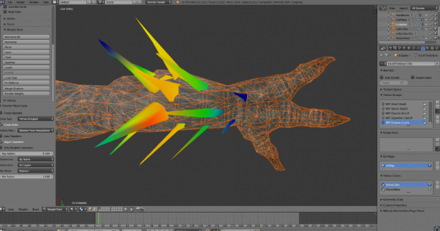
Unfortunately, when using the Weight Transfer tool to automatically rig the protrusions, they will often have different weights assigned at different sections of the protrusion, causing it to bend as the creature animates. This must be fixed manually.
- Use the Transfer Weight tool (see post above) to transfer weights from the body of the creature to the new protrusions (must be two separate objects in blender). You will probably see that each protrusion has a variety of weights (colors):
- Open the spike mesh in Edit mode. Select all vertices for a single spike. If the spikes aren't connected you can do this easily: select one vertex, then hold Ctrl and hit Numpad+ a few times.
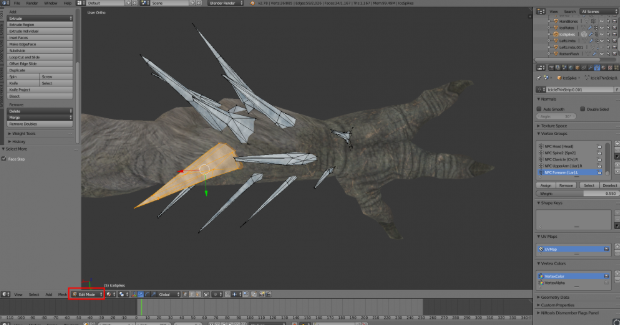
- Open the spike mesh in Weight Paint mode. Enable the option for Vertex Selection Masking. You should see yellow dots on the object you selected, and black dots everywhere else.
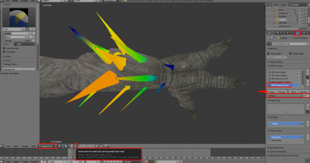
- Using the Vertex Groups section found in the Data tab, find all bones that are effecting this protrusion (any color other than the darkest blue, anywhere on the spike). I suggest using the arrow buttons to organize them so that they are all next to each other in the list.
- For one bone, set the weight of all selected vertices. You can type any weight into the area where it says "Weight:", then click Assign. But how do you know what number to type? This takes some trial and error:
- Look at the area where the spike meets the creature's skin. The color found here is the color you want. There may be some small range of colors in the area where the two meet, if so just choose an average color for this area. (If there is a wider range of colors this technique might result in some "sliding" when animated -- see the Sliding Fix below.)
- Give a guess for the number value of this color (Blue = 0, Teal = 0.25, Green = 0.5, Yellow = 0.75, Red = 1.0). Assign that value while watching the edge of the spike closely.
- If your guess was wrong (the color at the edge between spike and skin changes), hover your mouse over the render window and hit Ctrl+Z to undo the change. Type another number and try again. Repeat until you find an optimal weight.
After a successful Step 5, the spike's weight should blend perfectly where it connects to the skin, then maintain that exact color for the length of the spike: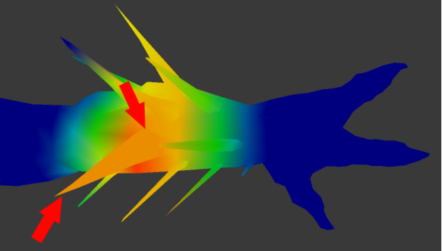
(To get this view, I'm merging the two meshes with Ctrl+J then viewing in weight mode. Then undo the merge with Ctrl+Z.)
- When this spike is appropriately rigged to ALL bones that affect it, choose another spike and repeat Steps 2-6.
The final result should look like this: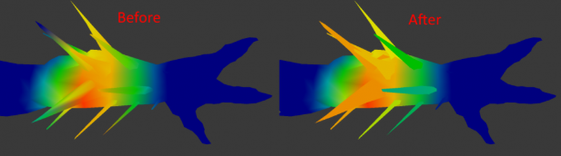


Sliding Fix
Now, as mentioned in Step 5a, there will sometimes be a "sliding" effect if you completely rigidify a spike that had a wide range of bone weights at its base and is in a separate object from the skin beneath it. The spike will stay solid while the flexible skin moves in various directions, giving the appearance that the spike is not attached to the skin.
In these cases, you may want to leave the vertices near the skin with their initial weights from the Weight Transfer tool, and only edit the weights for vertices that don't directly touch the skin.
In Step 2, just only select the vertices that are far from the surface of the skin, then proceed like normal. Here you can see that I only selected the 7 farthest vertices of this spike and left the remaining vertices untouched:
That's it! Once you've edited all of your protrusions, your model should be ready for export!

Solid Plate Rigging[edit]
Solid plates of non-flexible material on an armor or creature can be a tricky problem. On the one hand, the plate should obviously have a single weighting across it to prevent it from stretching.
But on the other hand, if that plate doesn’t stretch at all, then the vertices around it are going to have to do extra stretching to compensate. And if the plate is not part of the same object as the underlying stretchy skin, if you decide to make it rigid you will have to adjust the nearby skin weighting to prevent sliding effects. In the end you will have to find a compromise that looks good to you. You might even have to re-topologize a bit to make sure your vertices are in good places to distinguish between those that should stretch and those that shouldn’t.
Combining Bones[edit]
Sometimes, the best course of action is for a section of your model to move as the average of two or more bones. For example, if you want a creature’s tongue to appear lifted when the mouth is open, but lower a bit as the mouth closes, you might make the entire tongue use the 50% average of the Skull bone and the Jaw bone. The entire tongue will then move as a solid unit and seem almost as if it has its own bone, but that bone will behave precisely as an average of the other two bones.
Additionally, you can get sometimes get interesting effects by rigging partially to a completely different part of the body. For example, my Vvardvark is based on the chicken skeleton, which does not have a tail. To make the tail appear animated, I partially rigged it to the head bone, so the tail would appear to counter-balance the weight of the head: when the Vvardvark looks left, its tail tilts slightly right. Since the tail is so far from the head, I used only a tiny amount of weighting (the further from a bone, the more exaggerated its movements become). This also made it important that any cross-section of the tail has different weights than the cross-sections in front of or behind it: if the end of the tail had a single amount of weighting for the Head bone, the rigging to the head would be obvious as a sudden bend and then straightening of the tail.